IGNITION SYSTEM
Ignition Harness. Unless the harness assembly is in obviously new condition and is known to have been recently installed, it is recommended that the harness be replaced at overhaul.
CYLINDERS, PISTONS AND VALVE TRAIN
Inspect all cylinder, piston and valve train parts.
Cylinder Head (Visual Inspection).
Examine the cylinder head thoroughly, checking for the following
possible defects.
a. Loose, scored, pitted or otherwise damaged valve seats. (Mark for replacement).
b. Loose or damaged studs. (Replace with 0.003, 0.007 or 0.012 oversize studs).
c. Loose or damaged spark plug heli-coil inserts. (Mark for replacement with oversize insert.
d. Loose, cracked or scored valve guides. (Mark for replacement).
e. Nicked, scored or dented mounting pads. (Intake and exhaust ports, rocker box covers.)
f. Cooling fins. The following standards shall prevail insofar as acceptance or rejection of cylinder heads are concerned.
Physically damaged, broken or bent fins.
(a) The blended area for any one fin shall not exceed 3/8 square inches, nor 3/8 inch in depth.
(b) No more than two blended areas on any one fin.
(c) No more than four blended fins on the push rod side of the head. No more than six blended fins on
the anti-push rod side of the head.
(d) In addition to the above, it is recommended that a fluorescent penetrant inspection of the cylinder be made. Pay particular attention to the following areas.
(1) Between the 15th and 20th cylinder fin (counting from the top) on exhaust port side of cylinder.
(2) The area around the lower spark plug
Cylinder Head (Dimensional Inspection).
Check the ID of each intake valve guide (it is recommended that exhaust valve guides be replaced at overhaul) with the flat plug rejection gage (ST-81). Check the diameter and outof- roundness of the guide bore by checking with the gage at a minimum of two position 900 apart. If the gage enters the guide at any of the positions tested, mark the guide for replacement.
Cylinder Barrel (Visual Inspection).
In addition to a thorough inspection of the cylinder barrel to ascertain its general condition, make the following specific checks.
a. Cooling Fins. It is recommended that notches or nicks be profiled with a hand grinder or file. A cracked cylinder barrel is cause for rejection of the cylinder.
b. Cylinder Skirt. Replace any cylinder having a bent, cracked, broken or corroded skirt,
c. Check mounting flange for cracks, nicks, warping, or corrosion.
d. Inspect interior of barrel for scoring or corrosion. Minor damage can be repaired by regrinding or honing; deep scoring or pitting, however, is cause for rejection of the cylinder.
e. Inspect interior of nitrided barrel for barrel glaze and a possible ring wear step at the point where the piston reverses travel at the top of the stroke.
Cylinder Barrel (Dimensional Inspection).
Dimen-sional inspection of the barrel consists of the following measurements (the numbers in parenthesis refer to the ap-plicable reference numbers in the Table of Limits):
a. Fit between piston skirt and cylinder (519).
b. Maximum taper of cylinder walls (520).
c. Maximum out-of roundness (521). c. Maximum out-of-roundness (521).
d. Bore diameter (522).
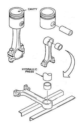
Piston (Visual Inspection).
Examine the top of the piston for excessive pitting, cavaties or surface distortion. The latter may be evidence of detonation, particularly if the piston has been in service for a relatively short time. Other critical points which must receive thorough visual examination are the piston ring lands and grooves, piston pin holes, and piston pin holes bosses.
Piston (Dimensional Inspection).
Make the following dimensional checks on each piston (the numbers in paren- thesis refer to the applicable reference numbers in the Table of Limits).
Table of Limits
a. Side clearance between piston ring and piston (514,515 and 516). Pistons for Lycoming opposed engines are ground with a slight taper from the skirt to ground with the exception of the lands between the the head, with the exception of the lands between the top compression and oil control rings, which are ground parallel.
b. Inside diameter of piston pin hole (512).
c. Clearance between piston skirt and cylinder and piston diameter at top and bottom (519).
Piston Pin and Piston Pin Plugs.
Check OD of piston pin against ID of hole in piston (reference 512, Table of Limits). Measure fit between piston and plugs and check OD of plugs (reference 513, Table of Limits). Examine interior
surfaces of piston pin for corrosion or pitting. Valve Rockers. Damaged, badly worn, pitted or
scored top and push rod sockets warrant replacement of the rocker. Rockers that are scored at the point of contact with the fulcrum must be replaced.
Push Rods.
Inspect push rods for wear or looseness of ball ends. If ball ends are loose, replace the rod. Rod must be straight within .010 inch.
Valves.
Remove the valves from the cylinder and clean to remove soft carbon and examine visually for physical damage, damage due to burning or corrosion. Valves that indicate damage of this nature must not be reused.
OIL SUMP AND FUEL INDUCTION
Oil Suction Screen.
Before cleaning the screen, inspect for evidence of metal particles, which could serve as an aid to locate deterioration in some section of the engine. Inspect the screen for distortion or openings of the mesh.
Carburetors.
Inspection of carburetors must determine parts serviceability and repair and replacement requirements. Check applicable manufacturer's publications for limits to be used when conducting inspection.
CRANKCASE, CRANKSHAFT & RECIPROCATING PARTS
Inspect all crankcase, Specific instructions follow.
Bearings (Precision Type).
AU precision type bearing inserts used for main crankshaft bearings and connecting rod bearings should be replaced with new bearing inserts at overhaul.
Crankcase (Visual Inspection).
Check carefully for burrs, nicks and cracks around the bearing support webs. Check bearing bores and inspect tang slots for any roughness that might case improper seating of bearing inserts. Check all drilled holes.
Fretting on the contacting surfaces of the hearingsaddle supports in the crankcase occurs on some engines. This condition is caused by slight motion between the contacting surfaces and results in erosion of the metal surface.The affected areas have tiny pit holes and a frosted appearance. as contrasted to adjacent shiny unaffected surfaces. This condition can be misleading because of its trivial appearance: nevertheless it can be the cause of severe engine damage.
Fretting, by inself in this area. does not appreciably damage the structure of the metal. but the metal removed by the fretting action does change the size of the bearing saddles sufficiently to cause loose thru-studs and undersize main bearing bares. If not detected during overhaul.
excessively tight crankshaft bearing fits will result with eventual engine failure.
Crankshaft (Visual Inspection).
Carefully inspect all surfaces of the shaft for cracks. checking the baring surfaces with particular care for scoring, galling, corrosion, pitting or other damage.
Crankshaft (Dimensional Inspection).
Place the crankshaft in Vee blocks supported at the locations called out in Table of Limits and using a surface plate and dial indicator measure the run-out at center main bearings. If this total indicator reading exceeds the dimensions given in reference 556 the shaft must not be reused. The crankshaft flange run-out may be checked at this time and if the total indicator reading exceeds the run-out given in Table of Limits (reference 607) the shaft must be rejected.
Using new inserts at all main bearing locations,assemble crankcase halves together, temporarily torque all thru-bolts to 300 inch pounds and measure the ID of the bearings. Measure the OD of the crankshaft main bearing journals and compare the resulting clearances
with the Table of Limits (reference 501). Assemble the connecting rods temporarily (using new bearing inserts)and check the crankpin journal clearances in the same manner, see Table of Limits. If clearances
do not fall within prescribed limits, the shaft must be brought undersize. See Repair and Replacement section for instructions for regrinding.
Camshaft (Visual Inspection).
Carefully inspect all surfaces of the camshaft for cracks, scoring, galling, cor-rosion, pitting or other damage; be particularly careful when inspecting bearing surfaces. If a hydraulic lifter has been rejected for spalling, inspect the corresponding cam lobe. Any indication of distress, surface irregularity or feathering at the edge of the cam lobe is cause for rejec-tion of the camshaft.
Camshaft (Dimensional Inspection).
Support the camshaft in Vee blocks at its front and rear bearing jour-nals and check the run-out at the center bearing location.
See Table of Limits Slight bending opera-tions are permissible on the camshaft providing careful magnetic inspection follows such procedures. Measure the diameter of the camshaft bearing journals and check them against the bearings formed by the crankcase. Table of Limits.
Connecting Rods (Dimensional Inspection).
Discard all connecting rod bolts and nuts; new bolts and nuts are to be used on assembly.Check condition of bore in large end for seating of the bearing inserts. Check bore in small end of bushing with connecting rod bushing plug gage (P/N 64537). If the gage enters the bushing, bushing must be replaced.
Connecting Rod Parallelism Check.
Using connecting rod parallelism and squareness gage(P/N 64530), insert tapered sleeves (1 and 2) in bearing holes in connecting rod. Be sure that bearing cap is assembled properly and securely tightened. Place arbors (3 and 4) through sleeves (1 and 2 respectively) and place gage arm to exact distance between arbors and lock the adjusting screw with nut . Then remove gage arm, place
it on other end of arbor, and check distance between ar- bors. For exact parallelism or alignment, the distances checked on both sides will be the same. See reference 566, Table of Limits.
Connecting Rod Squareness Check.
Using the same gage that was used in the parallelism check described above, place parallel blocks (1) on surface plate and, with sleeves and arbors still in place in connecting rod, place ends of arbor on parallel blocks. Check clearance at points (2) where arbors rest on parallel blocks, using a feeler gage. For exact squareness or zero twist, no clearance will exist at the designated points.
Counterweight Bushing
Wear in the counterweight bushing is usually evident as out-of-round on the inside diameter. Check each bushing with the bore gage P/N ST-73. The diameter should be between .7485 and .7505inch. Out of-round should not exceed .0005 inch. The ST-73 gage is specially made so that it can be set with a micrometer. If the diameter of any bushing is oversize, or excessively out-of-round all the bushing in the counterweight must be replaced.
Crankshaft Counterweight Bushing. Wear or damage to the crankshaft counterweight bushing ,
located in the crankshaft counterweight lobes is almost impossible to detect by normal inspection procedures. Because of this situation and as damage to the counterweight bushing could cause failure to the counterweight and/or the crankshaft, it is mandatory that these bushings be replaced at overhaul.
 dye penetrant,

